Kumite Electronic Speed Game
Introduction
The attack techniques of Karate as punches and kicks, during a fight (kumite) must always be used with the utmost speed but with maximum control in contact with the opponent.
It is important to the competitive Karate Skin Touch, being able to throw a punch with maximum speed and with the right choice of time only lightly touching the skin of the opponent.
For this reason was thought to study an electronic device able to coach the responsiveness and control techniques of attack.
This system is proving to be effective for people with different skills, eg. people who unfortunately find themselves on the chair in the kumite can work with this device.
A first idea
Project Description
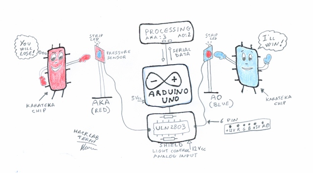
The game called Kumite Electronic Speed Game is constituted by an electronic card mod. Arduino UNO, used to measure the pressure exerted on two targets and turn on the LED lights.
The LED light devices are used to signal to the players is the instant when to attack those who come first in hitting the target.
If there is excessive contact with the target, the LED light will flash to indicate a loss of control.
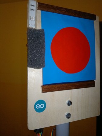
The pressure sensors are self-built using a particular resistive material called Velostat.
At the following link [[https://dev.hacklabterni.org/projects/diy-pressure-sensor/wiki]] you can find the instructions for the construction of pressure sensors with the Velostat.
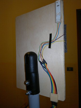
Installation pressure sensors and Strip Led
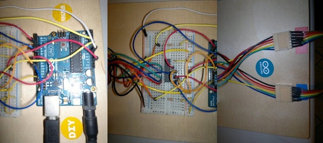
Arduino UNO with breadboard and connectors
Processing
Software to display the force exerted on the pressure sensors, the score of the players and buttons to start the game and reset scores was developed using Processing.
Below you can see a screenshot of the software.
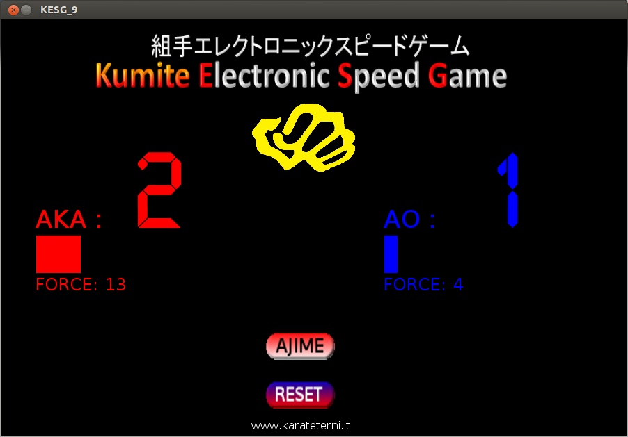
Implementation of the Project
To realize this game you need the following components:
- No. 1 Arduino UNO
- No. 1 ULN 2803
- No. 2 resistors 3.3 Kohm
- No. 1 breadboard
- No. 2 StripLed RGB with 3 LEDs.
- No. 1 Power supply 12 VDC
- No. 2 Pressure Sensor size 10x10 Cm.
- Nr 2 boards plywood size 20x15 cm
- Nr 2 telescopic poles to adjust height targets.
- No. 2 square bases to lock the telescopic sticks.
- No. 2 cable 6-pin to 4 m
- Nr 4 6-pin connectors
Connection Diagram
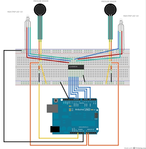
Light control and Pressure Sensor
To obtain the analog signal from the pressure sensors has been used a voltage divider. The pressure sensor has a resistance of about 3 K ohms, and then was put in series with a resistance of 3.3 K ohms .
Lights controlo has been used ULN2803 chip .
The ULN2803A is a high-voltage, high-current Darlington transistor array. The device consists of eight npn Darlington pairs that feature high-voltage outputs with common-cathode clamp diodes for switching inductive loads. The collector-current rating of each Darlington pair is 500 mA. The Darlington pairs may be connected in parallel for higher current capability.
More information here : [[http://www.ti.com/lit/ds/symlink/uln2803a.pdf]]
Problems encountered during testing
The pressure sensors, handcrafted, if not pasted on the back panel may lose traction and therefore not properly report the moment of contact and the pressure exerted.
On the panel of the pressure sensor cables with 6-pin must be fixed on the rod support, otherwise you may experience desoldering .
The support rod of the panels must be well blocked by hitting otherwise may be generated excessive oscillations.